Flame Rectification

Flame rectification requires a 240 volt ac electrical supply and is a very quick, safe and reliable way of detecting the presence of a flame.
The alternating current (ac) produces a sine wave which alternates from positive to negative and back again. Each complete wave is called a `cycle' and a 240 volt ac supply produces 50 cycles per second, hence 240 volts ac 50 Hertz.

Flame rectification occurs when the burner of the combi ignites and the ions in the flame allow the current to flow. The flame works as a rectifier creating a small dc current which is sensed by the electronics of the boiler.
The flame acting as a rectifier works in a similar way to that of a non- return valve only allowing flow in one direction in this case current only flows in the positive half of the cycle and is therefore known as half wave rectification.
In effect what will happen is that the burner of the combi will become positively and negatively charged in turn as the current alternates.
The pilot or main burner has a substantially larger surface area than the ignition electrode so when the burner is ignited positive ions are attracted to the negatively charged burner and so the current flows through the lit flame and on to earth.
The original ac is rectified to dc through the flame, and this is known as partial or half wave rectification.
The small dc charge produced by the flame is sensed by the electronics on the pcb and allows the ignition sequence to continue by stopping the production of the spark and energising the main gas valve of the boiler to allow heating demand to be met.
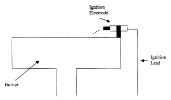
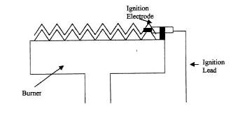
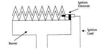
The drawings below show the different stages of the ignition process and the importance of the correct positioning of the ignition electrode should be apparent.

Certain manufacturers prefer to use a second electrode to sense the presence of a flame and in this case the second sensor is known as a 'flame sensing or rectification probe'.
The positioning of the probes will vary from manufacturer to manufacturer but the basic principles remain the same as at the end of the day the process is designed to produce and sense safe and satisfactory ignition of the burner.

| 
| 
| 
| 
|